SUMMARY
|
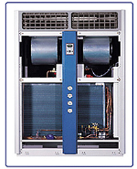
As industrial technology is highly developed, the importance of product's precision and experiment adaptable to surrounding environment is increasing every day. Sugong Tech's Constant Temperature and Humidity Chamber is introduced to keep the constant temperature and humidity of the area client designated. This equipment is designed to be available in any place with such features as maximum heat efficiency, miniaturization, lightweight, anti-vibration, silent operation, fine shape and color. We have applied many types to our products such as AIRCOOLED, WATER COOLED, GLYCOL COOLED, and CHILLED WATER and CPU CHILLER systems |
 T/H Room Design Checkpoints
 |
1. The outer wall surface should not be in direct light. 2. Heat-resistance processing should be performed if direct light is unavoidable. 3. Windows should not be installed if possible as their overall heat transmission level is higher than that of a wall. 4. A lobby should be installed at the entrance of a constant temperature & humidity air-conditioning room. 5. The inside and outside of a wall should be structured to prevent condensation. 6. The room should be structured to prevent temperature/humidity differences caused by infiltration of external air. 7. Heat load calculation should be done with a maximum load in simultaneous operation mode for summer, mid-year and 8. Calculate the capacity required to maintain the set temperature and humidity within the standard time by analyzing 9. Although the difference in the indoor temperature/humidity decreases with higher frequency of ventilation, 10. Positive pressure should be maintained to prevent outside air from entering. Entry of outside air should be minimized |
 Standard State of a Constant Temperature & Humidity Air-Conditioning Room
| Class | Standard temperature/humidity | Permitted difference |
|
Standard temperature level 1 Standard temperature level 2 Standard temperature level 3 Standard temperature level 4 |
20ˇÉ | ˇľ1ˇÉ ˇľ2ˇÉ ˇľ5ˇÉ ˇľ10ˇÉ |
|
Standard humidity level 1 Standard humidity level 2 Standard humidity level 3 |
65% | ˇľ2ˇÉ ˇľ5ˇÉ ˇľ10ˇÉ |
Temperature/Humidity Standards for Different Areas| Area | Dry-bulb temperature(ˇÉ) | Relative humidity(%) |
|
Precision measurement room Electric measuring device Ample production Syrup production Chemical storage room Plastic-related process Fiber-related process MIL specs Film storage room |
20 23, 20 27 27 0~5 23 20 23, 25 16 |
58 35~75 30 35 56~60 50 55 45~55 45 |